

PIR Detector Performance Testing
Fresnel Factory measures how far, how wide and how strongly a PIR detector actually senses a moving human target — using an automated 5-axis CNC test system and a temperature-controlled scaled dummy, instead of a person walking across a room.
Summary
- What it is: engineering performance testing of assembled PIR (passive infrared) detectors, PIR lenses and other infrared sensing devices.
- Standards referenced: IEC 63180, and EN 50131-2-2 (the part of the EN 50131 series covering passive infrared detectors), security grades 1 to 4.
- Test system: 5-axis CNC automated positioner, 1:5 scaled human dummy with numerically controlled section temperatures.
- Coverage: up to 45 m detection diameter, 360° in a single measurement cycle, up to 12 m mounting height.
- Repeatability: 98.5% demonstrated.
- Turnaround: typically 2 to 4 weeks.
- Who it is for: any manufacturer with a PIR detector in development or production — we do not need to have designed the lens.
- Status: engineering evaluation, not accredited certification.
- Two services have their own pages: pet and wildlife immunity testing (SPT-F) and quarterly detection conformance monitoring (DCM).
- Which test do you need?
- Why an assembled detector must be measured
- SPT-A — Angular Signal Profile (threshold tuning)
- SPT-R — Detection Range Report (IEC 63180)
- SPT-S — Security Detector Evaluation (EN 50131-2-2)
- What you receive — sample report
- Test system specification
- How a test project runs
- What you need to send
- Pricing and what is included
- Frequently asked questions
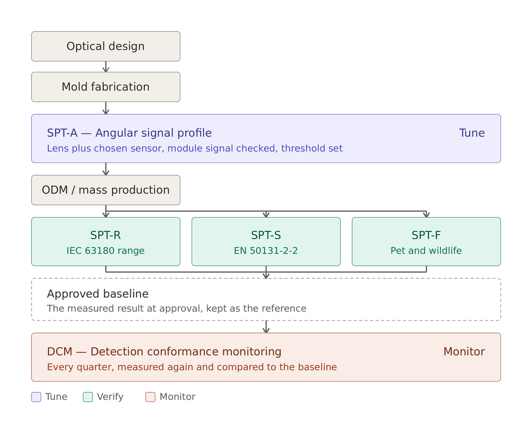
Which PIR test do you need?
Pick by the stage you are at: SPT-A tunes a new module, SPT-R and SPT-S verify a finished product against a standard, SPT-F verifies an animal-immunity claim, and DCM watches for drift once you are in production.
| Service | Purpose | The question it answers | Typical buyer | When |
|---|---|---|---|---|
| SPT-A Angular Signal Profile |
Tune | What signal does my module actually receive, and what threshold and delay time suit it? | Firmware / software engineer | First samples off a new mold |
| SPT-R Detection Range Report |
Verify | How far and how wide does my detector see, measured to IEC 63180? | Development engineer | Production samples |
| SPT-S Security Detector Evaluation |
Verify | Does my detector hold up under EN 50131-2-2 movement conditions, at the grade I am targeting? | Compliance / certification lead | Before booking an accredited lab |
| SPT-F False-Alarm Immunity Test |
Verify | Is the pet-immunity figure on my datasheet supported by measured data? | Product manager / marketing | Any time the claim is published |
| DCM Detection Conformance Monitoring |
Monitor | Does my product still meet the performance it was approved at? | Quality manager | Every quarter, in production |
Why does an assembled PIR detector need to be measured?
Because detection range and detection area are not properties of the sensor alone. They are produced by the lens, the sensor position, the enclosure, the electronic circuit and the sensitivity settings acting together.
A PIR sensor element by itself cannot form a defined detection direction or detection area. The Fresnel lens does two things: it concentrates infrared energy from a chosen direction onto the sensor element, extending detection distance, and it divides the space in front of the detector into detection and non-detection zones. When a person crosses from a non-detection zone into a detection zone, the incident infrared energy changes and the detector produces a signal.
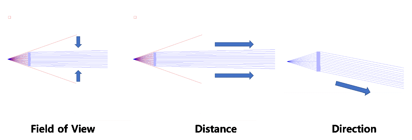
That means the same sensor element, behind two different lenses, gives two different products. And the lens itself does not always behave as designed:
- Optical design — the position, angle and focal characteristics of each lens segment decide where detection zones land. Differences show up more clearly at the periphery than at the centre.
- Lens material — internal infrared transmittance varies with material, colour, additives and thickness, changing how much energy reaches the sensor.
- Mold manufacturing — Fresnel lenses need smooth optical surfaces, so mold machining quality feeds directly into sensing performance.
Why an automated test instead of a walk test
IEC 63180 and EN 50131-2-2 both specify test conditions for motion detector evaluation, including movement speed and travel distance. Running those conditions with a real person requires a large test space and a long measurement time, and differences in walking speed and gait between operators change the result. Two runs are not comparable.
Automated measurement replaces the person with a movable dummy that simulates a human target. Heaters in the head, torso and leg sections hold defined temperatures representative of a human body. The detector is fixed at a specified position and height, the dummy is driven at a specified speed, and the system records detection position together with the sensor output signal. The result is stable conditions, reproducible data and far less measurement time.
SPT-A — Angular Signal Profile
Module signal measurement and threshold tuning support Tune
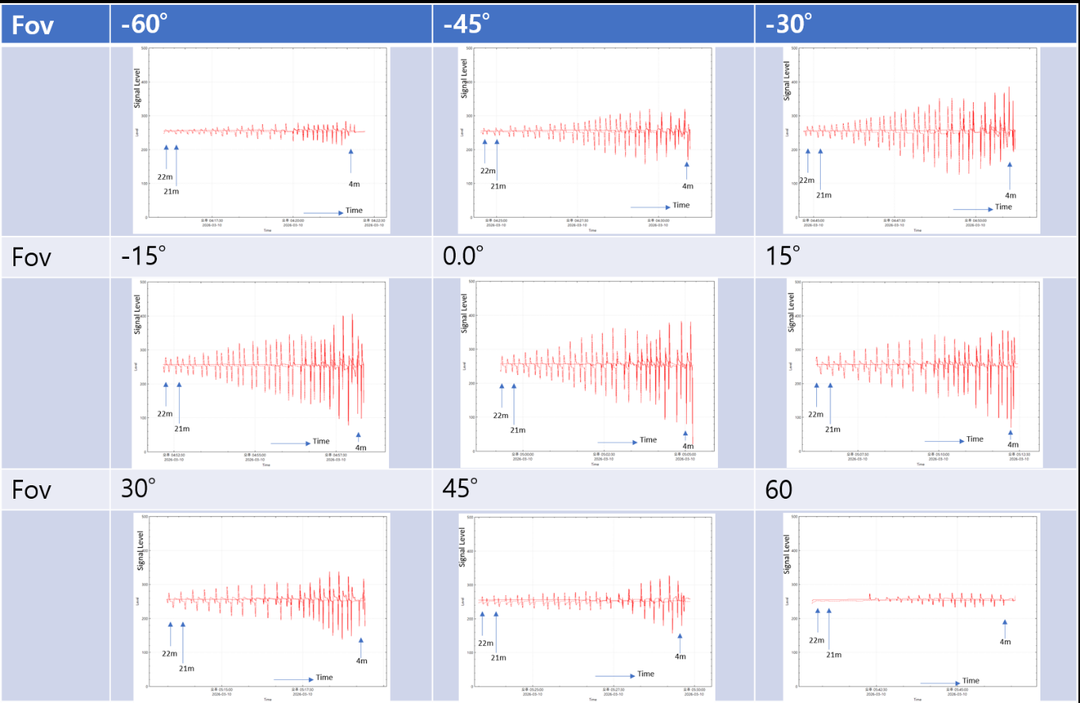
SPT-A records the actual signal your sensor module receives, at several angles across the field of view, so that threshold and delay time can be set from measured data instead of from trial and error in the field.
The detector is measured as a complete module — lens, the sensor you have selected, the circuit and the enclosure together. The dummy is driven at a specified speed and the sensor output is recorded continuously as relative signal strength against movement time, repeated at several field-of-view angles. What comes back is the shape of the signal, not a pass or fail verdict.
Standard angle set — 14 angles
A standard SPT-A engagement measures 14 angles, in one of two ways:
- a 140° sector swept in 10° steps, or
- 14 angles you specify, distributed across the full field of view of the device under test.
The second option suits detectors whose field of view is wider or narrower than 140°, or where you already know which zones matter. Additional angles beyond 14 are quoted separately.
What you receive
- Signal waveform for each of the measured angles
- Peak values, and centre-zone versus edge-zone comparison
- The observed margin between motion signal and background
- Reference data for evaluating Threshold and Delay Time settings
Where it helps
- Setting Threshold and Delay Time against the real movement speeds your product must catch
- Finding where in the field of view your noise margin is thinnest
- Comparing two lens candidates against the same sensor, under identical conditions
- Checking that a detection zone actually produces the sensor signal it was designed to produce
SPT-R — Detection Range Report (IEC 63180)
Detection distance and detection area to IEC 63180 Verify
SPT-R measures where a moving target is detected and plots the result as a detection map, following the test conditions defined in IEC 63180.
IEC 63180 — Methods of measurement and declaration of the detection range of detectors — Passive infrared detectors for major and minor motion detection — was published by the International Electrotechnical Commission in June 2020. It allows a scaled test dummy for automated testing at different mounting heights, which is what makes a 45 m detection diameter measurable indoors.
Tests performed
| Test | Method |
|---|---|
| Radial motion | The target starts as far from the detector as the setup allows and moves toward it until detection occurs; the detection range is recorded. The table then rotates 10° and the measurement repeats until the full detection area is covered. |
| Tangential motion (major motion) | Grid cells of 1 m square as defined in the standard (0.2 m square at 1:5 scale). |
| Tangential small movement | Small-movement detection within the detection area. |
| Detection boundary | Tangential dummy movement with rotation angle −5° to +5° as defined in the standard. |
What you receive
- A test report stating the device under test, test procedure, setup and conditions
- A plot for each test — radial, boundary and tangential small movement
- A comprehensive combined detection map
- Idealised detection areas expressed as diameters, ready for a declaration of detection range
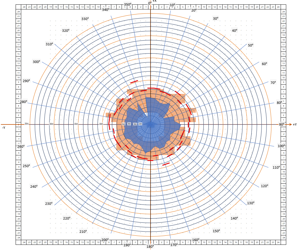
Test conditions can be scaled to your product. A recent report, for example, covered a detector at a 4.6 m (15 ft) installation height with a 44 m (145 ft) maximum range and a 1 m/s target speed, measured at a 5:1 scale ratio.
SPT-S — Security Detector Evaluation (EN 50131-2-2 based)
Movement-condition testing for intrusion detectors Verify
SPT-S runs an intrusion detector through the movement speeds and travel distances defined in EN 50131-2-2 and returns a grid-based map of where the detector responded and where it did not.
EN 50131-2-2 is the part of the EN 50131 series that covers passive infrared detectors for intrusion and hold-up alarm systems. The sibling parts cover other detection technologies — EN 50131-2-3 for microwave, EN 50131-2-4 for combined PIR and microwave, and so on. Our testing is for PIR, so EN 50131-2-2 is the relevant part.
Security grades 1 to 4
EN 50131-2-2 provides for security grades 1 to 4 and environmental classes I to IV. The grade changes the requirements — target speeds, detection coverage and feature set all tighten as the grade rises, and Grade 3 and above add anti-mask requirements.
We are not limited to any single grade. The test conditions are configured to the grade you are targeting. The SPT machine drives the target from very low speeds up to 25 km/h, which covers the movement-speed requirements of every grade in the standard, and the grid resolution and measurement area are set per test rather than fixed.
Grade 2 and above normally require testing in an independent laboratory, which is slow and expensive to repeat. SPT-S is designed to be run before that: a fast engineering evaluation that finds the failure while it is still cheap to fix.
Example scenario set
The scenarios below are an example configuration from a customer project, not a fixed menu. Speeds, areas and travel distances are set to the grade and installation condition being evaluated.
| Scenario | Target speed | Measurement area | Travel distance |
|---|---|---|---|
| Human detection on the field-of-view boundary | 1 m/s | Customer-specified boundary | 3 m |
| Human detection within the boundary | 0.5 m/s | 22.5 m × 40 m | 3 m |
| Human detection within the boundary, high velocity | 2 m/s | 22.5 m × 40 m | 3 m |
| Human detection close in | 0.5 m/s | 2 m × 3 m | 3 m |
What you receive
- A grid map of detection and non-detection points across the specified boundary
- The same map across the full measurable field
- Close-in and high-velocity response results
- Consistency of response across repeated runs

What you receive — a look at the actual report
Every test returns a written report with the test conditions stated, a plot for each test performed, and a combined result you can act on. Below are pages from a real IEC 63180 report, with the customer's identifying details removed.
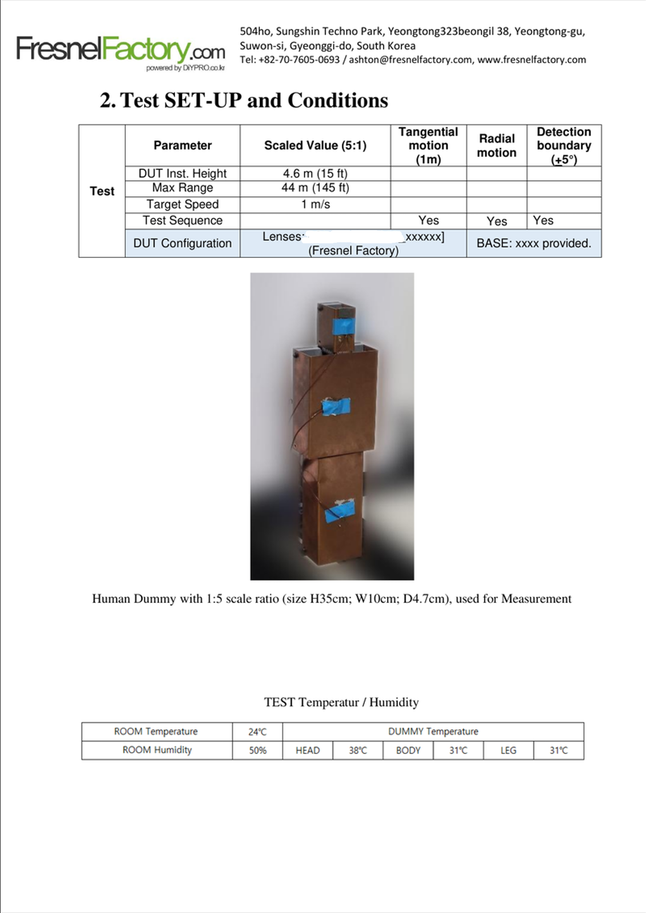
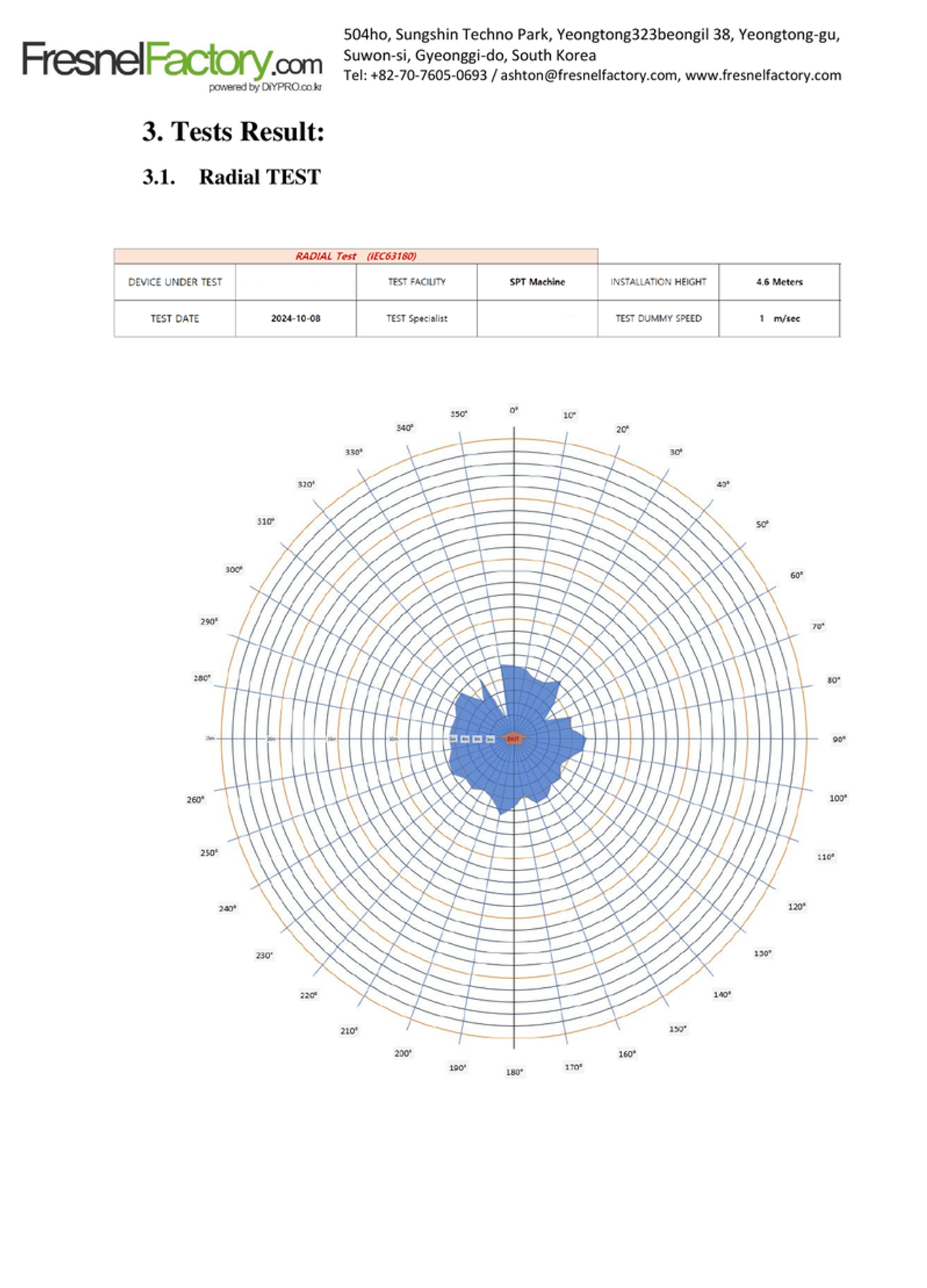
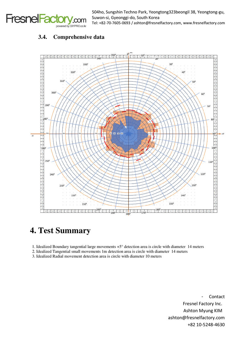
What a test report contains
- Device under test — what was tested, in what configuration, with which lens and settings
- Test procedure — which standard clauses were followed, and any agreed deviation stated explicitly
- Test setup and conditions — scale ratio, installation height, maximum range, target speed, test sequence, ambient temperature and humidity
- Results — a separate plot for each test performed
- Comprehensive data — the combined detection map
- Test summary — the measured result stated in plain numbers, such as idealised detection areas expressed as diameters
Reports are delivered as PDF. Underlying measurement data can be supplied on request in a tabular format for your own analysis.
False-alarm immunity and production monitoring
Two further services sit outside the development-project group above, because they answer different questions for different people.

SPT-F — False-Alarm Immunity Test Verify
Most PIR datasheets carry a pet-immunity figure — 20 kg, 85 lb, 80 cm height. Very few are backed by measured data, because a live animal will not repeat a defined path at a defined speed.
SPT-F uses temperature-controlled animal dummies on the same CNC stage to measure the ratio between the human signal and the animal signal at the same position: your discrimination margin. Indoor and outdoor products both apply, because the specification is written in mass and height, not species.

DCM — Detection Conformance Monitoring Monitor
Approval-day performance is not guaranteed to survive two years of production. Mold wear, resin lot changes, supplier changes and production-condition drift all move a Fresnel lens, and nothing in the industry routinely checks it.
DCM is an annual programme that re-measures your product every quarter and compares it against its approved baseline. Your detector does not have to be one we designed.
Test system specification
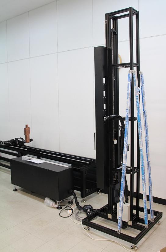
The Scaled Performance Test (SPT) machine is a 5-axis CNC automated test system that measures a motion detector through a full 360° circle in a single measurement cycle.
| Measurable distance | 22.5 m / 74 ft (wall mounted) · 45 m / 147 ft (ceiling mounted) |
| Measurable field of view | 360° |
| Maximum installation height | 12 m / 39 ft |
| Maximum target speed | 25 km/h / 15.5 mph |
| Angular resolution | 0.1° |
| Linear resolution | 0.1 mm / 0.0039 in |
| Position accuracy | 0.1 mm / 0.0039 in |
| Temperature resolution | 0.1 °C |
| CNC control | 5 axis |
| Scale ratio | 1:5 |
| Demonstrated repeatability | 98.5% |
| Test targets | Human dummy (1:5 scale, per IEC 63180) · animal dummies for SPT-F |
| Typical turnaround | 2 to 4 weeks |
Scaled test dummy
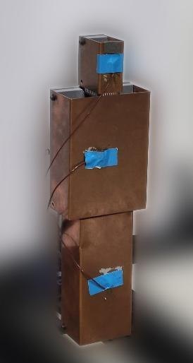
Testing at different mounting heights uses a scaled test dummy, which IEC 63180 permits for automated testing. A 1:5 scaled dummy is acceptable with the head held at 14 K above ambient temperature and the body and legs at 7 K above the ambient temperature of the test room. Head, torso and leg sections are numerically temperature controlled, and the whole assembly is driven by the CNC positioner rather than carried by an operator.
Mounting and fixtures
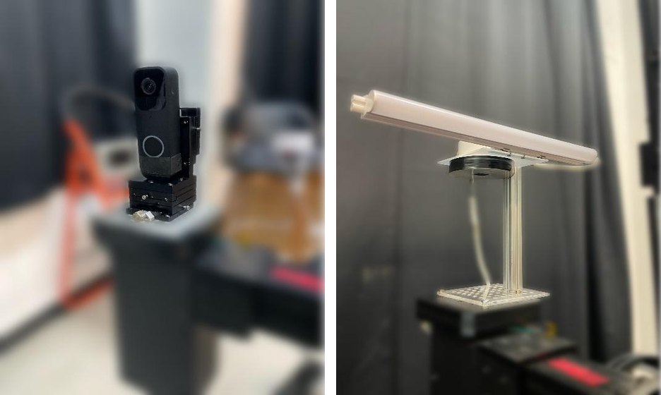
Devices under test are held in 3D-printed holders made for the specific product, and can be measured in wall-mounted or ceiling-mounted configurations. Custom measurement conditions — mounting height, tilt, target speed, grid resolution, angular step — can be set to match your product rather than the other way round.
How a test project runs
- Tell us the product and the question. Detector type, mounting height and tilt, intended detection distance and area, and which of the services above fits.
- We confirm test conditions. Scale ratio, target speed, grid resolution, angular step, mounting configuration, ambient conditions. Anything non-standard is agreed in writing before we start.
- You send the device under test. A complete, assembled detector is preferred, because the measurement is of the whole system. Send the sensitivity settings you want measured.
- We measure. Automated run on the SPT machine under the agreed conditions.
- You receive the report — typically 2 to 4 weeks from receipt of samples.
Where testing fits in a lens development programme
If we are also designing your lens, performance evaluation is an optional step in the standard development process: customer request review → NRE quotation → optical design → customer design approval → mold fabrication → sample supply → performance evaluation → customer sample approval → mass production preparation → mass production. If we are not, that changes nothing about the test — we measure detectors regardless of who designed the optics.
What you need to send
Send complete, working detectors with power and signal wiring already attached, plus the mechanical and setting information we need to hold and configure them. The one requirement people miss is that SPT-A needs access to signal strength, not just the ON/OFF output.
| Item | What we need |
|---|---|
| Samples | Two or more units recommended. One unit can be measured, but two or more let us separate unit-to-unit variation from the effect you are actually trying to see — which matters most when you are comparing lens candidates or chasing a marginal result. |
| Power | Supply voltage anywhere in the 3 V to 24 V range. Tell us the voltage, the current draw and how you want it connected. |
| Signal wiring | Please prepare wires that let us read the sensor signal, not only the ON/OFF detection output. This is what makes an angular signal profile possible. Bring the leads out of the enclosure so they can be connected without opening the unit on our bench. |
| Settings | How Threshold, Delay Time and sensitivity are set, and the values you want measured. If a configuration tool or app is required, send it with the samples. |
| Mechanical | Outline dimensions and mounting details, so we can produce a 3D-printed holder for your product. A STEP or drawing file is ideal. |
| Installation intent | The mounting height and tilt the product is designed for, and the detection distance and area it is supposed to achieve. Without this we cannot tell you whether it met its target. |
| Documents | Datasheet or specification, and the lens part number if known. |
| Shipping | Tell us whether samples should be returned or disposed of after testing. We will confirm the shipping address and the customs description to declare. |
SPT-R, SPT-S and SPT-F can be run from the normal ON/OFF detection output, because those tests record where detection occurred. The signal-strength requirement applies to SPT-A, and to the discrimination-margin part of SPT-F.
Pricing and what is included
Prices below are list prices for one product configuration, and include setup, the measurement itself and the written report.
| Service | What the price includes | List price |
|---|---|---|
| SPT-A Angular Signal Profile |
14 measurement angles — a 140° sector in 10° steps, or 14 angles you specify across the full field of view. One lens and sensor combination, one settings configuration. Signal waveform per angle, peak values, centre versus edge comparison. |
USD 1,500 |
| SPT-R Detection Range Report |
One set of four tests — radial motion, tangential motion, tangential small movement, detection boundary. Radial in 10° steps, tangential on 1 m grid cells, boundary at −5° to +5°, per IEC 63180. One mounting configuration. Full test report with combined detection map. |
USD 3,000 |
| SPT-S Security Detector Evaluation |
Four scenarios configured to your target security grade — boundary detection, within-boundary, within-boundary at high velocity, close-in. One mounting configuration. Grid maps for each scenario. |
USD 4,500 |
| SPT-F False-Alarm Immunity Test |
Human and animal targets measured over the same grid, with the discrimination margin reported. | USD 5,000 |
| DCM Detection Conformance Monitoring |
Annual programme, four quarterly checks against your approved baseline, per product configuration. Baseline characterisation is a separate one-off measurement. | USD 5,000 / year |
Quoted separately
So there are no surprises in the invoice, the following sit outside the list price and are quoted before work starts:
- Measurement angles beyond the standard 14 (SPT-A)
- Additional settings configurations — for example the same detector measured at two threshold settings
- Additional devices under test beyond the units needed for the standard run
- Additional mounting configurations, such as measuring the same product wall-mounted and ceiling-mounted
- Non-standard test conditions — custom grid resolution, custom angular steps, speeds or areas outside the standard set
- Scenarios added beyond the four in SPT-S
- Expedited turnaround ahead of the normal 2 to 4 weeks
- Return shipping, where samples are to be sent back
Bundled pricing is available when several services run on the same device in one session, and when testing is attached to a lens development project with us. Ask for a written scope with the quotation — we will state the angles, configurations and mounting conditions the price covers.
Looking for something more specific?
- SPT-F — Pet and wildlife immunity testing →
If your datasheet carries a pet-immunity figure and you need measured data behind it. Indoor and outdoor. - DCM — Quarterly detection conformance monitoring →
If your product is already in production and you need to know it still meets the performance it was approved at.
Start a test
Tell us the detector, the mounting condition and what you need to prove. We will tell you which test answers it and what the report will show.
Email ashton@fresnelfactory.com Send a request
Global: Ashton Myung Kim · ashton@fresnelfactory.com · +82 70-7605-1652
USA: Frank Yim · frank.yim@fresnelfactory.com · +1 925-457-1758
Frequently asked questions
What is IEC 63180?
IEC 63180 is an International Electrotechnical Commission standard published in June 2020, titled Methods of measurement and declaration of the detection range of detectors — Passive infrared detectors for major and minor motion detection. It defines how detection range is measured and declared, and permits a scaled test dummy for automated testing at different mounting heights.
What is the difference between an IEC 63180 test and an EN 50131-2-2 test?
IEC 63180 measures and declares detection range for passive infrared detectors generally — how far and how wide the detector sees. EN 50131-2-2 is the European standard for PIR detectors used in intrusion alarm systems, and is concerned with whether the detector responds under defined movement conditions at a given security grade. Choose IEC 63180 for a general motion or presence detector, and EN 50131-2-2 for a security or intrusion product.
Which EN 50131 security grades can you test?
All of them. EN 50131-2-2 provides for security grades 1 to 4, and the grade changes the requirements rather than the standard. We configure target speed, grid resolution and measurement area to the grade you are targeting. The test system drives the target from very low speeds up to 25 km/h, covering the movement-speed requirements of every grade. Note that the final “-2” in EN 50131-2-2 identifies passive infrared detectors, not a grade.
Why EN 50131-2-2 and not another part of EN 50131?
The EN 50131-2 series is split by detection technology. EN 50131-2-2 covers passive infrared detectors, EN 50131-2-3 covers microwave, EN 50131-2-4 covers combined passive infrared and microwave, and further parts cover opening contacts, glass break and shock detectors. We test passive infrared detection performance, so EN 50131-2-2 is the applicable part.
Is this accredited certification?
No. Testing at Fresnel Factory is engineering evaluation and pre-compliance testing. It is fast and affordable precisely because it is not an accredited certification process. Use it to find and fix problems before you pay for accredited certification; formal certification must be carried out separately under the required procedure.
Do you need to have designed my lens?
No. We measure PIR detectors, PIR lenses, TMOS modules and other infrared sensing devices regardless of who designed the optics or where they were manufactured.
What do I need to send for testing?
Two or more complete detectors are recommended, with power and signal wiring already brought out. Supply voltage can be anywhere from 3 V to 24 V. Send the mechanical dimensions so we can print a holder, the intended mounting height and tilt, how the Threshold and Delay Time are set, and any configuration tool the product needs. See what you need to send for the full list.
Does SPT-A require an analog output from my module?
No, not necessarily. SPT-A needs to read signal strength rather than only the ON/OFF detection decision, and an analog test point ahead of the comparator is the most common way to expose that. But any output that lets signal strength be read per angle is acceptable, including a digital or serial output that reports the sensor level. Send us the interface description and we will confirm feasibility before quoting.
How many measurement angles does SPT-A include?
Fourteen. The standard set is either a 140° sector swept in 10° steps, or 14 angles you specify across the full field of view of the device under test. The second option suits detectors whose field of view is wider or narrower than 140°. Angles beyond 14 are quoted separately.
What is included in the price?
Setup, the measurement and the written report, for one product configuration. Each service has a defined scope — 14 angles for SPT-A, four tests for SPT-R, four scenarios for SPT-S. Additional angles, extra settings configurations, extra mounting configurations, non-standard conditions and expedited turnaround are quoted separately and agreed before work starts. See pricing and what is included.
Can I see a sample report before ordering?
Yes. Pages from a real IEC 63180 report, with the customer's identifying details removed, are shown under what you receive, and we can send the complete anonymised sample report on request.
Should I send a lens or a complete detector?
A complete, assembled detector. Detection performance is produced by the lens, sensor position, enclosure, circuit and sensitivity settings together, so measuring the lens alone does not tell you what the product will do. If you are comparing lens candidates, send the same assembled module with each lens fitted.
How long does a PIR detector performance test take?
Typically 2 to 4 weeks from receipt of the samples, depending on the number of scenarios and devices. Automated measurement is what makes this possible — a 360° measurement is completed in a single cycle.
What is a scaled test dummy, and why use one?
A scaled test dummy is a reduced-size thermal target that stands in for a human body, with head, torso and leg sections held at defined temperatures above ambient. At 1:5 scale, a 45 m detection diameter and a 12 m mounting height become measurable in a practical indoor space, and every run repeats the same path at the same speed — which a human operator cannot do.
How repeatable are the results?
98.5% repeatability has been demonstrated across repeat measurements of the same lens. Positioning is controlled to 0.1 mm and 0.1°, and dummy section temperatures to 0.1 °C.
Can you measure animal or pet immunity?
Yes. SPT-F measures detector response to temperature-controlled animal dummies and reports the discrimination margin between the human signal and the animal signal at the same position. See pet and wildlife immunity testing.
How much does PIR detector testing cost?
List prices start at USD 1,500 for an angular signal profile (SPT-A), USD 3,000 for an IEC 63180 detection range report (SPT-R) and USD 4,500 for an EN 50131-2-2 based security evaluation (SPT-S). Non-standard
Fresnel Factory Inc. has specialised in Fresnel optics since 2002, covering optical design, mold tooling, injection molding and measurement for infrared sensing devices. Head office: Yeongtong-ro 323beon-gil 38, Suwon-si, Gyeonggi-do 16676, South Korea.